


FEATURES
23• Low Supply-Voltage Range, 1.8 V to 3.6 V • On-Chip Comparator
• Ultra-Low Power Consumption • Supply Voltage Supervisor/Monitor With
– Active Mode: 270 µA at 1 MHz, 2.2 V Programmable Level Detection
– Standby Mode • Brownout Detector (VLO): 0.3 µA
– Off Mode • Bootstrap Loader (RAM Retention): 0.1 µA
• Serial Onboard Programming, No External • Ultra-Fast Wake-Up From Standby Mode in
Less Than 1 µs Programming Voltage Needed, Programmable
Code Protection by Security Fuse • 16-Bit RISC Architecture, 62.5-ns Instruction
Cycle Time • Family Members Include:
• Basic Clock Module Configurations: – MSP430F233
– – 8KB+256B Flash Memory, Internal Frequencies up to 16 MHz
– Internal Very Low-Power LF Oscillator – 1KB RAM
– 32-kHz Crystal – MSP430F235
– Internal Frequencies up to 16 MHz With – 16KB+256B Flash Memory
Four Calibrated Frequencies to ±1% – 2KB RAM
– Resonator – MSP430F247, MSP430F2471 (1)
– External Digital Clock Source – 32KB+256B Flash Memory
– External Resistor – 4KB RAM
• 12-Bit Analog-to-Digital (A/D) Converter With – MSP430F248, MSP430F2481
Internal Reference, Sample-and-Hold, and – 48KB+256B Flash Memory
Autoscan Feature
– 4KB RAM
• 16-Bit Timer_A With Three Capture/Compare
– MSP430F249, MSP430F2491
Registers
– 60KB+256B Flash Memory
• 16-Bit Timer_B With Seven Capture/Compare
– 2KB RAM With Shadow Registers
– MSP430F2410 • Four Universal Serial Communication
Interfaces (USCI) – 56KB+256B Flash Memory
– USCI_A0 and USCI_A1 – 4KB RAM
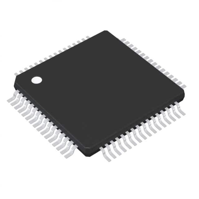
– Enhanced UART Supporting Auto-Baudrate • Available in 64-Pin QFP and 64-Pin QFN
Detection Packages (See Available Options)
– IrDA Encoder and Decoder • For Complete Module Descriptions, See
MSP430x2xx Family User’s Guide (SLAU144)
– Synchronous SPI
– USCI_B0 and USCI_B1
(1) The MSP430F24x1 devices are identical to the MSP430F24x – I
2C™ devices, with the exception that the ADC12 module is not
– Synchronous SPI

